SAT (Separating Axis Theorem)

Posted on January 01, 2010

This is a post I have been meaning to do for some time now but just never got around to it. Let me first start off by saying that there are a ton of resources on the web about this particular collision detection algorithm. The problem I had with the available resources is that they are often vague when explaining some of the implementation details (probably for our benefit).

I plan to explain the algorithm and also fill in some of the blanks that I had when implementing this myself.

First let me start off by saying there is a great tutorial here with interactive flash examples.

  1. Introduction
  2. Convexity
  3. Projection
  4. Algorithm
    1. No Intersection
    2. Intersection
  5. Obtaining The Separating Axes
  6. Projecting A Shape Onto An Axis
  7. Finding the MTV
  8. Curved Shapes
  9. Containment
  10. Other Things To Note

Introduction

The Separating Axis Theorem, SAT for short, is a method to determine if two convex shapes are intersecting. The algorithm can also be used to find the minimum penetration vector which is useful for physics simulation and a number of other applications. SAT is a fast generic algorithm that can remove the need to have collision detection code for each shape type pair thereby reducing code and maintenance.

Convexity

SAT, as stated before, is a method to determine if two convex shapes are intersecting. A shape is considered convex if, for any line drawn through the shape, that line crosses only twice. If a line can be drawn through the shape and cross more than twice the shape is non-convex (or concave). See Wiki’s definition and MathWorld’s definition for more formal definitions. So lets look at some examples:

Figure 1: A convex shape
Figure 2: A non-convex shape

The first shape is considered convex because there does not exist a line that can be drawn through the shape where it will cross more than twice. The second shape is not convex because there does exists a line that crosses more than twice.

SAT can only handle convex shapes, but this is OK because non-convex shapes can be represented by a combination of convex shapes (called a convex decomposition). So if we take the non-convex shape in figure 2 and perform a convex decomposition we can obtain two convex shapes. We can then test each convex shape to determine collision for the whole shape.

Figure 3: A convex decomposition

Projection

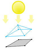
The next concept that SAT uses is projection. Imagine that you have a light source whose rays are all parallel. If you shine that light at an object it will create a shadow on a surface. A shadow is a two dimensional projection of a three dimensional object. The projection of a two dimensional object is a one dimensional “shadow”.

Figure 4: A Projection (or shadow)

Algorithm

SAT states that: “If two convex objects are not penetrating, there exists an axis for which the projection of the objects will not overlap.

No Intersection

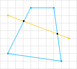
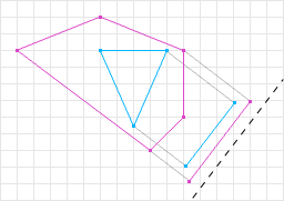
First lets discuss how SAT determines two shapes are not intersecting. In figure 5 we know that the two shapes are not intersecting. A line is drawn between them to illustrate this.

Figure 5: Two Separated Convex Shapes

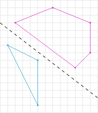
If we choose the perpendicular line to the line separating the two shapes in figure 5, and project the shapes onto that line we can see that there is no overlap in their projections. A line where the projections (shadows) of the shapes do not overlap is called a separation axis. In figure 6 the dark grey line is a separation axis and the respective colored lines are the projections of the shapes onto the separation axis. Notice in figure 6 the projections are not overlapping, therefore according to SAT the shapes are not intersecting.

Figure 6: Two Separated Convex Shapes With Their Respective Projections

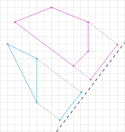
SAT may test many axes for overlap, however, the first axis where the projections are not overlapping, the algorithm can immediately exit determining that the shapes are not intersecting. Because of this early exit, SAT is ideal for applications that have many objects but few collisions (games, simulations, etc).

To explain a little further, examine the following psuedo code.

1
2
3
4
5
6
7
8
9
10
11
12
13
Axis[] axes = // get the axes to test;
// loop over the axes
for (int i = 0; i < axes.length; i++) {
  Axis axis = axes[i];
  // project both shapes onto the axis
  Projection p1 = shape1.project(axis);
  Projection p2 = shape2.project(axis);
  // do the projections overlap?
  if (!p1.overlap(p2)) {
    // then we can guarantee that the shapes do not overlap
    return false;
  }
}

Intersection

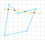
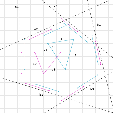
If, for all axes, the shape’s projections overlap, then we can conclude that the shapes are intersecting. Figure 7 illustrates two convex shapes being tested on a number of axes. The projections of the shapes onto those axes all overlap, therefore we can conclude that the shapes are intersecting.

Figure 7: Two Convex Shapes Intersecting

All axes must be tested for overlap to determine intersection. The modified code from above is:

1
2
3
4
5
6
7
8
9
10
11
12
13
14
15
16
Axis[] axes = // get the axes to test;
// loop over the axes
for (int i = 0; i < axes.length; i++) {
  Axis axis = axes[i];
  // project both shapes onto the axis
  Projection p1 = shape1.project(axis);
  Projection p2 = shape2.project(axis);
  // do the projections overlap?
  if (!p1.overlap(p2)) {
    // then we can guarantee that the shapes do not overlap
    return false;
  }
}
// if we get here then we know that every axis had overlap on it
// so we can guarantee an intersection
return true;

Obtaining The Separating Axes

The first question I had when implementing this algorithm was how do I know what axes to test? This actually turned out to be pretty simple:

The axes you must test are the normals of each shape’s edges.

Figure 8: Edge Normals

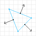
The normals of the edges can be obtained by flipping the coordinates and negating one. For example:

1
2
3
4
5
6
7
8
9
10
11
12
13
14
Vector[] axes = new Vector[shape.vertices.length];
// loop over the vertices
for (int i = 0; i < shape.vertices.length; i++) {
  // get the current vertex
  Vector p1 = shape.vertices[i];
  // get the next vertex
  Vector p2 = shape.vertices[i + 1 == shape.vertices.length ? 0 : i + 1];
  // subtract the two to get the edge vector
  Vector edge = p1.subtract(p2);
  // get either perpendicular vector
  Vector normal = edge.perp();
  // the perp method is just (x, y) =&gt; (-y, x) or (y, -x)
  axes[i] = normal;
}

In the method above we return the perpendicular vector to each edge of the shape. These vectors are called “normal” vectors. These vectors are not normalized however (not of unit length). If you need only a boolean result from the SAT algorithm this will suffice, but if you need the collision information (which is discussed later in the MTV section) then these vectors will need to be normalized (see the Projecting A Shape Onto An Axis section).

Perform this for each shape to obtain two lists of axes to test. Doing this changes the pseudo code from above to:

1
2
3
4
5
6
7
8
9
10
11
12
13
14
15
16
17
18
19
20
21
22
23
24
25
26
27
28
29
Axis[] axes1 = shape1.getAxes();
Axis[] axes2 = shape2.getAxes();
// loop over the axes1
for (int i = 0; i < axes1.length; i++) {
  Axis axis = axes1[i];
  // project both shapes onto the axis
  Projection p1 = shape1.project(axis);
  Projection p2 = shape2.project(axis);
  // do the projections overlap?
  if (!p1.overlap(p2)) {
    // then we can guarantee that the shapes do not overlap
    return false;
  }
}
// loop over the axes2
for (int i = 0; i < axes2.length; i++) {
  Axis axis = axes2[i];
  // project both shapes onto the axis
  Projection p1 = shape1.project(axis);
  Projection p2 = shape2.project(axis);
  // do the projections overlap?
  if (!p1.overlap(p2)) {
    // then we can guarantee that the shapes do not overlap
    return false;
  }
}
// if we get here then we know that every axis had overlap on it
// so we can guarantee an intersection
return true;

Projecting A Shape Onto An Axis

Another thing that wasn’t clear was how to project a shape onto an axis. To project a polygon onto an axis is relatively simple; loop over all the vertices performing the dot product with the axis and storing the minimum and maximum.

1
2
3
4
5
6
7
8
9
10
11
12
13
double min = axis.dot(shape.vertices[0]);
double max = min;
for (int i = 1; i < shape.vertices.length; i++) {
  // NOTE: the axis must be normalized to get accurate projections
  double p = axis.dot(shape.vertices[i]);
  if (p < min) {
    min = p;
  } else if (p > max) {
    max = p;
  }
}
Projection proj = new Projection(min, max);
return proj;

Finding the MTV

So far we have only been returning true or false if the two shapes are intersecting. In addition to thi,s SAT can return a Minimum Translation Vector (MTV). The MTV is the minimum magnitude vector used to push the shapes out of the collision. If we refer back to figure 7 we can see that axis C has the smallest overlap. That axis and that overlap is the MTV, the axis being the vector portion, and the overlap being the magnitude portion.

To determine if the shapes are intersecting we must loop over all the axes from both shapes, so at the same time we can keep track of the minimum overlap and axis. If we modify our pseudo code from above to include this we can return a MTV when the shapes intersect.

1
2
3
4
5
6
7
8
9
10
11
12
13
14
15
16
17
18
19
20
21
22
23
24
25
26
27
28
29
30
31
32
33
34
35
36
37
38
39
40
41
42
43
44
45
46
47
48
49
50
double overlap = // really large value;
Axis smallest = null;
Axis[] axes1 = shape1.getAxes();
Axis[] axes2 = shape2.getAxes();
// loop over the axes1
for (int i = 0; i < axes1.length; i++) {
  Axis axis = axes1[i];
  // project both shapes onto the axis
  Projection p1 = shape1.project(axis);
  Projection p2 = shape2.project(axis);
  // do the projections overlap?
  if (!p1.overlap(p2)) {
    // then we can guarantee that the shapes do not overlap
    return false;
  } else {
    // get the overlap
    double o = p1.getOverlap(p2);
    // check for minimum
    if (o < overlap) {
      // then set this one as the smallest
      overlap = o;
      smallest = axis;
    }
  }
}
// loop over the axes2
for (int i = 0; i < axes2.length; i++) {
  Axis axis = axes2[i];
  // project both shapes onto the axis
  Projection p1 = shape1.project(axis);
  Projection p2 = shape2.project(axis);
  // do the projections overlap?
  if (!p1.overlap(p2)) {
    // then we can guarantee that the shapes do not overlap
    return false;
  } else {
    // get the overlap
    double o = p1.getOverlap(p2);
    // check for minimum
    if (o < overlap) {
      // then set this one as the smallest
      overlap = o;
      smallest = axis;
    }
  }
}
MTV mtv = new MTV(smallest, overlap);
// if we get here then we know that every axis had overlap on it
// so we can guarantee an intersection
return mtv;

Curved Shapes

We have seen how polygons can be tested using SAT, but what about curved shapes like a circle? Curved shapes pose a problem for SAT because curved shapes have an infinite number of separating axes to test. The way this problem is usually solved is by breaking up the Circle vs Circle and Circle vs Polygon tests and doing some more specific work. Another alternative is to not use curved shapes at all and replace them with high vertex count polygons. The second alternative requires no change to the above pseudo code, however I do want to cover the first option.

Let’s first look at Circle vs Circle. Normally you would do something like the following:

1
2
3
4
5
6
7
Vector c1 = circle1.getCenter();
Vector c2 = circle2.getCenter();
Vector v = c1.subtract(c2);
if (v.getMagnitude() < circle1.getRadius() + circle2.getRadius()) {
  // then there is an intersection
}
// else there isnt

We know two circles are colliding if the centers are closer than the sum of the circle’s radii. This test is actually a SAT like test. To achive this in SAT we could do the following:

1
2
3
4
5
6
Vector[] axes = new Vector[1];
if (shape1.isCircle() && shape2.isCircle()) {
  // for two circles there is only one axis test
  axes[0] = shape1.getCenter().subtract(shape2.getCenter);
}
// then all the SAT code from above</pre>

Circle vs Polygon poses more of a problem. The center to center test along with the polygon axes is not enough (In fact the center to center test can be omitted). For this case you must include another axis: the axis from the closest vertex on the polygon to the circle’s center. The closest vertex on the polygon can be found in a number of ways, the accepted solution using Voronoi regions which I will not discuss in this post.

Other curved shapes are going to be even more of a problem and must be handled in their own way. For instance a capsule shape could be decomposed into a rectangle and two circles.

Containment

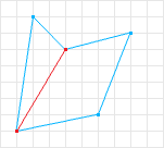
One of the problems that many developers choose to ignore is containment. What happens when a shape contains another shape? This problem is usually not a big deal since most applications will never have this situation happen. First let me explain the problem and how it can be handled. Then I’ll explain why it should be considered.

Figure 9: Containment

If one shape is contained in another shape SAT, given the pseudo code we have so far, will return an incorrect MTV. Both the vector and magnitude portions may not be correct. Figure 9 shows that the overlap returned is not enough to move the shapes out of intersection. So what we need to do is check for containment in the overlap test. Taking just the if statement from the above SAT code:

1
2
3
4
5
6
7
8
9
10
11
12
13
14
15
16
17
18
19
20
21
22
23
24
25
26
if (!p1.overlap(p2)) {
  // then we can guarantee that the shapes do not overlap
  return false;
} else {
  // get the overlap
  double o = p1.getOverlap(p2);
  // check for containment
  if (p1.contains(p2) || p2.contains(p1)) {
    // get the overlap plus the distance from the minimum end points
    double mins = abs(p1.min - p2.min);
    double maxs = abs(p1.max - p2.max);
    // NOTE: depending on which is smaller you may need to
    // negate the separating axis!!
    if (mins < maxs) {
      o += mins;
    } else {
      o += maxs;
    }
  }
  // check for minimum
  if (o < overlap) {
    // then set this one as the smallest
    overlap = o;
    smallest = axis;
  }
}

Reason #1: It IS possible that the shapes could get in this type of configuration. Not handling this would require two or more iterations of SAT to resolve the collision depending on the relative sizes of the shapes.

Reason #2: If you plan to support Line Segment vs. Other shapes you have to do this because the overlap can be zero in some cases (this is due to the fact that a Line Segment is an infinitely thin shape).

Other Things To Note

Some other things to note:

  • The number of axes to test can be reduced by not testing parallel axes. This is why a rectangle only has two axes to test.
  • Some shapes like a rectangle can perform faster if it has its own projection and getAxes code since a rectangle doesn’t need to test 4 axes but really just 2.
  • The last separation axis could be used to prime the next iteration of SAT so that the algorithm could be O(1) in non-intersection cases.
  • SAT in 3D can end up testing LOTS of axes.
  • I’m not an expert and please excuse my terrible graphics.
Found an issue with this page? suggest edit

Comments

155 responses

Greg Atkinson

Hi I am very interested in your post on SAT. I found the post to be very clear and informing as I am currently trying to implement a SAT based collision test between a rectangle and a circle. My question has to do with projecting a shape on an axis, you made a note in your pseudo code that the axis should be normalized. How would you achive this?

In my case I am finding the axis that I want to project onto by taking the vector between the rectangles closest corner and the circles center (I only do this if the circles center is not directly over or next to the rectangle). This vector should define the axis that I want to project onto but how do I Normalize this? Am I just over complicating the issue, and should I normalize the vector by making it a unit vector?

Cheers Greg


William

No, you are on the right track. Normalization is the same thing as making it a unit vector:

Say your axis is the vector (3, 4) to normalize (i.e. make it a unit vector) just find the length:

l = sqrt(x2 + y2)
l = sqrt( 3 * 3 + 4 * 4 ) = 5

Then divide by the length

= (3/5, 4/5) = (0.6, 0.8)


ForrestUV

"The closest vertex on the polygon can be found in a number of ways, the accepted solution using Voronoi regions which I will not discuss in this post."

doh!!!
who can help me about using voronoi to find the closest vertex? :(


William

Checking what voronoi region a point lies in can be performed by a number of side of line tests. For instance the GJK algorithm uses this to determine where the origin is relative to the simplex. See my GJK post to get an idea.

It may not even be worth it if your polygons have a small number of vertices, especially in 2D. In fact, in my dyn4j project I use the brute force method and it never shows up on the profiler (mostly because you don't compare the distance, but instead the squared distance). This is only 5 operations per vertex (2 subtraction, 2 multiplication, and one addition). It would be difficult to beat this in the general case.


Mukkarum

First of all I would like to thank you for this tutorial. It is far clearer than many others that I have encountered online.

I was implementing separating axis, using this guide, and was curious about the implementation of Projection. Is the following how you would implement it? I am particularly concerned about getOverlap.

public class Projection {
  
  private final float m_min;
  private final float m_max;

  public Projection(float min, float max) {
    m_min = min;
    m_max = max;
  }

  public boolean doesOverlap(final Projection other) {
    if(m_max > other.m_min) {
      return true;
    }

    if(m_min > other.m_max) {
      return true;
    }

    return false;
  }

  public double getOverlap(final Projection other) {
    if(!doesOverlap(other)) {
      return 0;
    }

    if(m_max > other.m_min) {
      return Collider.getDistance(m_max, other.m_min);
    }
    else if(m_min > other.m_max) {
      return Collider.getDistance(m_min, other.m_max);
    }
    else {
      Log.warning("Bad case in getOverlap!");
      return 0;
    }
  }
}

William

Sorry I was away for a while and just now catching up. You can look at the implementation of the Interval class as an example.

But if you are anything like me you like to figure things out on your own. Here is what I would suggest, write down some examples for the different cases:
(0, 4) and (2, 6) normal case
(0, 3) and (4, 7) no overlap
(3, 6) and (0, 2) no overlap, reversed
(0, 3) and (3, 6) no overlap, "touching"
(0, 7) and (1, 4) overlap, containment
(0, 2) and (0, 2) same projection
etc.
and try out your methods.

For example, the method doesOverlap has some problems with example #3 that I have given since the first condition is true, yet the projections do not overlap.

As for the getOverlap method I can't really say since I'm not sure what Collider.getDistance is doing, but I'll try to answer. After the check to make sure the two projections overlap you only need to subtract two of the values:

For example if the projections are:
(0, 3) and (2, 30) then we only need to perform 3 – 2
Lets look at another case:
(4, 20) and (-1, 7) then we only need to perform 7 – 4
Lets look at another case:
(1, 10) and (2, 4) then we only need to perform 4 – 2
And another case:
(0, 3) and (3, 5) then we only need to perform 3 – 3
Lets look at one more case and you may see a pattern:
(-2, 6) and (-1, 10) then we only need to perform 6 – -1

I'll drop in a hint, it involves using max and min.

Thanks for the compliment btw,
William


Nick Wiggill

Thanks — nice, informative post.


I looked at your question you posted there and the answer given is pretty much correct.

However, to be safe its good to make sure you use the correct one, which depends on the winding of the polygon. If the winding of the polygon is Counter-Clockwise then you should use the normal that points right of the edge. If the polygon winding is clockwise, you should use the normal that points left of the edge. (This is why many engines require a winding direction of CCW or CW)

Referring to the really bad image above, and just using the edge (1, 1) to (2, 1.5) we get:

Vector p1 = new Vector(1, 1);
Vector p2 = new Vector(2, 1.5);

Vector edge = p2 - p1;
// edge is now (1, 0.5)

// => (-y, x) = (-0.5, 1)
Vector leftHandNormal = edge.left();

// => (y, -x) = (0.5, -1)
Vector RightHandNormal = edge.right();

If we used used the left hand normal for this edge we would get a normal that points in instead of out of the polygon. If we reverse the winding:

Vector p1 = new Vector(2, 1.5);
Vector p2 = new Vector(1, 1);

Vector edge = p2 - p1;
// edge is now (-1, -0.5)

// => (-y, x) = (0.5, -1)
Vector leftHandNormal = edge.left();

// => (y, -x) = (-0.5, 1)
Vector RightHandNormal = edge.right();

As we can see we would want to use the left normal in this case.


simpler

Refering to your last post William, how should I find out which normal I want?
Also:
The Y value gets bigger when it's going down in a coordinate system, how should I take that into account?


William

The normal that you want is the one that points outward from the polygon. So if we look at the example above, we want the right hand normal if the winding is anti-clockwise, and the left hand normal if the winding is clockwise.

We want the normal below (which is determined by the winding):

Yes, in Java2D (and I'm sure other language's 2D APIs) use a coordinate system that has (0, 0) at the top left corner of the window. You can use the same math:

If we place the above shape on that kind of coordinate system the two points would be:

Vector p1 = new Vector(1, 1);
// since the positive y-axis is pointing "down" the y coordinate
// for p2 will be 0.5 instead of 1.5
Vector p2 = new Vector(2, 0.5);

Vector edge = p2 - p1;
// edge is now (1, -0.5)

// => (-y, x) = (0.5, 1)
Vector leftHandNormal = edge.left();

// => (y, -x) = (-0.5, -1)
Vector RightHandNormal = edge.right();

Here we see that the edge that points outward from the shape is the left-hand normal.

Now if we think about this, we realy only need to use this coordinate system when drawing the shapes. You can store your coordinate data in any coordinate system you want. So, instead, I would suggest storing your shape/vector data in whatever coordinate system you are comfortable with, then we you go to draw everything transform the coordinate system so that it matches yours.

You can do this in Java2D like:

Graphics2D g = // get from the Canvas or whatever
// save the current transformation
AffineTransform old = g.getTransform();
// apply a translation transform to place (0, 0) in the center of the window
g.translate(width / 2, height / 2);
// apply a flip transformation to flip the y-axis
g.scale(1, -1);

// draw your stuff
// everything you draw here will be transformed from your
// coordinate system (typically called "world coordinates") to
// the window's coordinate system

// restore the old transformation
g.setTransform(old);

simpler

Thanks alot for the fast reply! I had alot of strugglings with understanding when the coordinate system where the top left corner is (0,0), but when you say that it only matters when drawing things really gets clearer.

I create my polygons in a counter clockwise order and after some figuring that left me with this

// side is the current side handled
// for a square side 1 = the left etc
axis.x = -(polygonA->pointList[side-1].y - polygonA->pointList[side].y);
axis.y = polygonA->pointList[side-1].x - polygonA->pointList[side].x;

What I don't understand from your example is this:

// for p2 will be 0.5 instead of 1.5
Vector p2 = new Vector(2, 0.5);

Why?

Thanks for a great guide and great replies btw!:)


William

Glad to hear that this helped you!

The reason p2 would change is because (assuming you used the window coordinate system, where (0, 0) is in the top left corner) is because y decreases instead of increases when you go "up."

p2 was (2, 1.5) in a normal coordinate system, but in this other one it would have been (2, 0.5) since we went up by 1 and up is in the negative direction.

But like I said, this isn't really important if you use a coordinate system you are comfortable with and then transform when drawing. The comment was only to show that the math still works, its just not as intuitive.

I also found some mistakes in my images for the winding, I fixed them.


heishe

I hope the author still somehow receives this comment:

Naturally, when I have two rectangles, this algorithm spits out the same overlaps+axis of the smallest displacement vector (since the two opposing edges of a rectangle are of course mathematically identical).

This creates a problem where the algorithm detects the optimal distance that one rectangle needs to be pushed in order to move it out of the rectangle that it's colliding with, but in one of two cases it finds the wrong direction in which it needs to be pushed ( namely the exact opposite from the direction in which it needs to be pushed).

Is there a way to fix that "bug" or is that a mathematical limitation that I need to accept in order to use this algorithm on rectangles?


William

If I understand you correctly, you are asking what to do when rectangles are aligned and they produce the same penetration but opposing directions. Like this:

Where

a = (1, 0) with a depth of 1 unit

And as you point out the blue rectangle will have nearly the same

b = (-1, 0) with a depth of 1 unit

What I would suggest is that you always return a vector that is pointing from shape A to shape B from SAT. This way you don't have to worry about which way the vector is pointing.

v = // the separation vector
ca = // shape a's center
cb = // shape b's center
cacb = cb - ca // the vector from ca to cb
if (v.dot(cacb) < 0) {
  // if the separation vector is in the opposite direction
  // of the center to center vector then flip it around
  // by negating it
  v.negate();
}

heishe

Hi.

First of all, thanks for the quick answer! That was very helpful and did exactly what I wanted.

Still, one bug/problem seems to be left for me: The algorithm seems to have problems with edges which are not axis-aligned. It both doesn't detect correct collision occurrence and as a result of that it also produces wrong minimal translation vectors.

I've searched for a long time now where the error in my code might be, but I just can't find it, so I guess I won't get around just posting my implementation here (it's in Java):

The main algorithm is this:

public static Vector2f doCollideEx(Box a, Box b)
	{		
		Projection2D p1,p2;
		float overlap = Float.MAX_VALUE;
		Vector2f axis = new Vector2f(0.0f,0.0f);
		
		Vector2f[] edge_normals = a.getEdgeNormals();
		for(int i=0;i<2;i++)
		{
			p1 = a.projectOnto(edge_normals[i]);
			p2 = b.projectOnto(edge_normals[i]);
			if(!p1.overlaps(p2))
				return new Vector2f(0.0f,0.0f);
			else
			{
				if(p1.getOverlap(p2)

Just as a little sidenote: The reason I'm running "i" only through 0 and 1 is of course that I only need to check the first two axis.

There are multiple custom classes used in that method, but I can assure you that all of them function correctly and produce correct values (I've tested them rigorously using various visualizations etc.). I also manually have to rotate the boxes when the user rotates them by a certain degree, but that code also works perfectly and produces correct values.

I'm pretty sure that the error is somewhere in my code where I project a box onto an axis (as in a.projectOnto(axis)), although I have no idea what might be wrong about it. It's part of the "Box" class, which is basically your shape class, just simplified to be a box:

	public Projection2D projectOnto(Vector2f axis)
	{
		float min = Float.MAX_VALUE;
		float max = Float.MIN_VALUE;
		
		for(int i=0;i max)
				max = dot;
			if(dot < min)
				min = dot;
		}
		return new Projection2D(min,max);
	}

Theoretically, my overlap code might also be producing values, but I have no idea how that could be:

	public boolean overlaps(Projection2D b)
	{
		return (!(b.right  this.right));
	}
	
	public float getOverlap(Projection2D b)
	{
		return (this.right < b.right) ? this.right - b.left : b.right - this.left;
	}

Sorry to bother you with lots of code, but I'm clueless right now and don't know how to fix it.


heishe

Oops, I just noticed, when I posted the comment I accidentally deleted out part of the projectionOnto code. This if the full one:

	public Projection2D projectOnto(Vector2f axis)
	{
		float min = Float.MAX_VALUE;
		float max = Float.MIN_VALUE;
		
		for(int i=0;i max)
				max = dot;
			if(dot < min)
				min = dot;
		}
		return new Projection2D(min,max);
	}

heishe

Oh damnit, another comment (sorry for that, but I can't edit).

I actually didn't delete anything, but the XHTML tags have problems with the smaller than and bigger than sign :) I'm going to post all the relevant code again, since the other code pieces also contain these signs:

	public static Vector2f doCollideEx(Box a, Box b)
	{		
		Projection2D p1,p2;
		float overlap = Float.MAX_VALUE;
		Vector2f axis = new Vector2f(0.0f,0.0f);
		
		Vector2f[] edge_normals = a.getEdgeNormals();
		for(int i=0;i<2;i++)
		{
			p1 = a.projectOnto(edge_normals[i]);
			p2 = b.projectOnto(edge_normals[i]);
			if(!p1.overlaps(p2))
				return new Vector2f(0.0f,0.0f);
			else
			{
				if(p1.getOverlap(p2)

heishe

Actually, nevermind at all! I've found the mistake, and it's so small and insignificant that I'm actually ashamed enough to not post it!

Thanks anyways :)


William

Sorry I couldn't get back to you sooner, but I'm glad that you found your problem. Don't be ashamed it's always the small mistakes in places that you never would look that cause problems (at least that's my experience).


William,

Your pseudo-code "Projecting a Shape Onto an Axis" have three mistakes:

01 double min = // really small number; Should be really large number instead
02 double max = // really large number; Should be really small number instead
...
08 } else if (p > max) { else is not needed
...

Other than that, great tutorial and working code!


William

Thanks, you are exactly right. I actually changed the code to initialize the min/max with the projection of the first vertex since that will be more robust anyway. Can't believe I missed that...

The else if on line 8 is actually required, otherwise the max would not be the max, it would be the last value that was not less than the min.

William


Severin

Very good article, thanks a lot! I'm implementing SAT in Java – very comfortable according to this pseudo-code example :)
But now, I'd like to handle SAT with non-convex polygons. According to the article, SAT can be applied to non-convex polygons, when we partition the polygon in convex parts (e.g. triangles) – quite obivous. Could anybody tell me, how to do this? I've been thinking about it for hours now, and haven't found a "satisfying" solution :P
There are also many suggestions (algorithms), but maybe someone could give me a concrete code example?
I'd be very glad about some useful inputs :)


Severin

08 } else if (p > max) { else is not needed

That's right, it should be:

if (p max) {
max = p;
}

Therefore an "if" but without an else. If the first value is the biggest value, he will be stored in min and would not be stored in max (because of the "else if").


William

That's right, i changed my code to set the min and max to the value of the first dot product on line 1 and 2. This allows the if/else to work as is.


William

Convex decomposition is a difficult subject to find readable papers on and simple examples for. I have implemented 3 different convex decomposition algorithms in the dyn4j project. Here are the names of the algorithms:

Ear Clipping
Bayazit
Sweep Line

The Ear Clipping and Sweep Line algorithms triangulate the polygon. To reduce the number of triangles there is another algorithm that can be used called Hertel-Mehlhorn that combines triangles into convex polygons.

The links here are just to give you a start. I had the least trouble in implementing the Ear Clipping and Bayazit algorithms.


Severin

Sorry, I didn't see that, I only read the comment of C :P

Thank you very much, that's exactly what I was searching for! I think, I'll try it first with the Ear Clipping-method.


I am trying to implement a SAT for triangles only and in 2D only, and this as a part of another assignment. I am a complete newbie in this area and I have been told to code in C.

This examples given here are pretty clear, although I am not sure what structures I would need in C.

For starters I thought,

typedef struct vertex {
int x, y;
}Vertex;

struct triangle {
Vertex v1, v2, v3;
};

would suffice. Is that correct? How can I define the axes structure?

Thanks...


William

You'll have to forgive me, my C/C++ is really REALLY rusty so ill try my best.

You can define the Axis struct/class exactly like the vertex one you have already. In most projects I've seen points, vertices and vectors use the same class since they all need to store x and y components. For instance:

struct Vector {
  double x, y;
}

struct Triangle {
  Vector v1, v2, v3;
  Vector* axes = new Vector[3];
}

Remember that an axis in the context of SAT is just a normalized vector.


Thanks for your prompt answer on my earlier comment.
I am not sure what the statement
if (!p1.overlap(p2))
would mean in context to my version of the problem. I am coding in C as I said in my last post.

When I obtain the dot product to get the min and max values for the projection, does it mean that projection p1 overlaps p2 if p1 < p2 or vice versa.

It would be great if you could let me know what exactly do we check in the method overlap() ?

Thanks!


William

The Projection class stores the minimum and maximum projections of the shape along d as it was explained here. So the overlap method of the Projection class tests whether the two projections overlap. For example, if the direction you were projecting on was (1, 0), you could get projections like this:

The overlap is the gray area where the two projections overlap or the difference between max1 and min2. So testing whether they overlap could be done by:

bool Projection::overlap(Projection* other) {
  return this->max > other->min
}

Unfortunately this condition is not sufficient. You can see that this fails in this case: p1 = (3, 6) and p2 = (0, 2) . The projections do not overlap (If you imagine these projections along the x-axis) but our overlap method will return true anyway. You can look at my implementation of the Projection class here. I call it Interval instead of Projection since I use it for other things.

From the source you can see that the overlap condition that I use is:

return !(this->min > other->max || other->min > this->max);

Why do you care if you use the normal that points in or the normal that points out? They are the same axis.


The reason we care is only when we want to do something with the collision information. For instance, if you wanted to push the shapes apart after detecting a collision you need the normal and depth. You could do something like move the first shape half of the depth along the normal and move the second shape half of the depth in the opposite direction. The problem is, you need to know which direction to move the first one. If you have the opposite direction normal (i.e. pointing inward instead of outward) then you will move the shapes closer together instead of apart.

In general, however, it doesn't really matter which ones you use because at the end you will probably check the direction of the normal anyway by doing something like this:

Vector n = // the normal from SAT;
Vector c1 = // the center point of the first shape;
Vector c2 = // the center point of the second shape;
Vector c1c2 = c2 - c1;
// check if the normal is in the direction of the center to center vector
if (c1c2.dot(n) < 0) {
  // if its in the opposite direction then flip it
  n.negate();
}

One of your comments under Obtaining The Separating Axes seems to be incorrect
// perform the perproduct to obtain the normal
You are not actually doing the perproduct here, you are just getting the normal/perpendicular. According to the tutorial you linked at the top the perproduct is a combination of getting the normal and doing the dot product but instead you are doing the dot product later on with your projections.

Additionally I think it would also help if you added the following afterwords as it would clarify what you are trying to do.

axes[i] = normal;

Thanks for your comments, you are exactly right about the perproduct. I fixed the post to reflect the correct operation that is performed. I also added the other snippet of code to the post to make things clearer.


Hi Williams
First of all thank you so much. This article was really helpful in implementing SAT.
However, I have a few questions for you.
1. I am trying to implement polygon-polygon, and polygon-circle contact detection for simulation gravity settling of these particles in a box. I have around 4000 particles, and initially i avoid containment. Also initially all the particles are pretty much overlapping with atleast one more particle. However, when i look at my final ensemble of these particles, I get a couple of particles that are floating. I mean they are not in contact with any other particle, and they just float in air. This is however not physical, since in reality you can't have floating particles in space. Do you have any suggestions ?


I may not be able to fix the floating particle problem without some source code. I'm assuming you are using a Circle shape for each particle? It sounds like you have the collision detection working, but the gravity isn't being applied to some of the particles? What are you doing when the particles collide with something?


Hi William

No I am not assuming circle shape for each particle. Initially I just inscribe the polygon within circles to give me some the centers of the polygons( All polygons are regular polygons). Yes I do have the collision detection and everything working. And you are right to some extend that I may not be applying the gravity enough. But even if I do that, I am implementing rigid boundary conditions at the corners of the box to push any particle that tries to leave the box. This might also be affecting the solution. But overall what I have observed is most of the particles touch each other, but there are say around 4-5 % of hexagonal particles in the system that do not contact anything..... If you have a mail ID or something I can send you the picture of my ensemble for you to have a look at ?
THanks for the reply


Hi William
When the particles collide with something, I first allow it to overlap, and then I use the mtv for each particle and I let it move to zero overlap.... Similar to what you have explained here.


Hello,
Great tutorial, I've been studying it and some others for a few days now. I've got almost everything figured out except when it comes to projecting a shape onto an axis.
In the section "Projecting A Shape Onto An Axis", on line 12 your wrote

Projection proj = new Projection(min, max);

What would that code entail? Do you now project the minimum onto the maximum value? But I suppose that wouldn't work since min and max are both doubles. I think this is the part thats getting me.
Thanks a lot!


Great to hear its helped! The Projection structure/class in this case is simply a storage structure, so something like this:

public class Projection {
  public double min;
  public double max;
  public Projection(double min, double max) {
    this.min = min;
    this.max = max;
  }
  public boolean isOverlapping(Projection p) {
    // test the overlap between this and 
    // p using their min and max properties
  }
}

Once we have the projection for shape A and shape B, say p1 and p2, we compare the two to see if they are overlapping.

p1.isOverlapping(p2);

See the comments above for more detail on how to know if two projections are overlapping.


Ahhhh, I see. One more question though. In some source code I found, the overlap of two rectangles is found by projecting each corner onto each axis. This is done with the following code:

private int GenerateScalar(Vector2 theRectangleCorner,
Vector2 theAxis)
{
  //Using the formula for Vector projection. 
  //Take the corner being passed in
  //and project it onto the given Axis
  float aNumerator = (theRectangleCorner.X * theAxis.X) + 
                     (theRectangleCorner.Y * theAxis.Y);
  float aDenominator = (theAxis.X * theAxis.X) + 
                       (theAxis.Y * theAxis.Y);
  float aDivisionResult = aNumerator / aDenominator;
  Vector2 aCornerProjected = new Vector2(
                       aDivisionResult * theAxis.X,
                       aDivisionResult * theAxis.Y);
            
  //Now that we have our projected Vector, 
  //calculate a scalar of that projection
  //that can be used to more easily do comparisons
  float aScalar = (theAxis.X * aCornerProjected.X) + 
                  (theAxis.Y * aCornerProjected.Y);
  return (int)aScalar;
}

Its in C#.

The values are then stored into a list and the minimums and maximums are found and checked for overlap. Is this the equivalent of doing the dot product of a corner and a normal?
I found this example here:
http://www.xnadevelopment.com/tutorials/rotatedrectanglecollisions/rotatedrectanglecollisions.shtml
if you are interested.

Thanks again for your help and the great comments. People like you are the reason I'm able to even sort of get a grasp of programming. I would not be able to do this on my own.


A rectangle is a special kind of polygon. It has 4 sides and by extension 4 normals to test. But, since the pairs of sides are parallel we can reduce the number of normals to test for a rectangle to just 2 (the link you sent tests all 4, but this isn't really a problem just a small performance enhancement).

If we allow rotation of the rectangle then we must test all the vertices. You can see this in the code in RotatedRectangle.cs lines 91-94.

As far as the code, if I translate into a more mathematical format:

private int GenerateScalar(Vector2 theRectangleCorner,
Vector2 theAxis)
{
  // this is the same as theRectangleCorner.dot(theAxis)
  // in essence this is finding the projection of the vector 
  // from the Origin to theRectangleCorner onto theAxis
  float aNumerator = (theRectangleCorner.X * theAxis.X) +
                     (theRectangleCorner.Y * theAxis.Y);
                     
  // this is the same as theAxis.dot(theAxis)
  // in essence this is finding the squared magnitude of the 
  // axis vector.  You don't need to do this unless theAxis
  // is not normalized
  float aDenominator = (theAxis.X * theAxis.X) +
                       (theAxis.Y * theAxis.Y);
                       
  // this is accounting for theAxis not being normalized
  // so doesnt need to be done if the axis is already 
  // normalized
  float aDivisionResult = aNumerator / aDenominator;
  
  // this is storing the projected point (not necessarily
  // the min/max).  My tutorial does not compute this as its
  // not necessary for SAT
  Vector2 aCornerProjected = new Vector2(
                       aDivisionResult * theAxis.X,
                       aDivisionResult * theAxis.Y);

  // this is performing theAxis.dot(aCornerProjected)
  // in essence this is finding the projection of the 
  // corner on the axis.  Later in the code, 
  // RotatedRectangle.cs lines 105-108, will set the 
  // min and max.  Its possible that this projection 
  // could be the min or the max
  // this line is equivalent to line 5 in my code in the
  // Projecting A Shape Onto An Axis section
  float aScalar = (theAxis.X * aCornerProjected.X) +
                  (theAxis.Y * aCornerProjected.Y);
  return (int)aScalar;
}

Very cool, I got it figured out. Thanks for your help! However, while I'm at it, do you know how to find the point where the rectangles collide and therefore the rotation necessary to further resolve the collision. For instance, say one rectangle is headed at another stationary rectangle at an angle. When they collide, the first rectangle will rotate flat against the second rectangle and slide off. Do you know or have any tutorials that explain how to carry out this calculation? I found this:
http://www.myphysicslab.com/collision.html
which is really cool but I find it difficult to follow and even more difficult to put to code. I've tried a bunch of different stuff on my own but can't seem to get anything that works under any circumstance. Sorry if I'm asking too much, but you're a really good resource and I'm eager to learn. Thanks again!


Awesome man! Finding the collision point and resolving the collision are difficult problems. I have a tutorial on a clipping algorithm that both dyn4j and box2d use to find collision points (there could be one or two depending on the configuration of the collision) that will work for any convex polygon.

Unfortunately, I don't have a tutorial (yet...) for collision resolution. The link you have is a great reference. The problem is inherently mathematical and complex. Today, most collision resolution software uses an impulse based solution (that's what's in the link you have). In that reference, equation 11 is the key, solving for j (the impulse), which will then be applied to both bodies to resolve the collision. You can apply the impulse to the bodies using equation 7, 8, 9 & 10.

This is probably one of the more simple tutorials as most attempt to deal with other issues like stacking. If you have any questions about the article there don't hesitate to ask here.


HI will
im a student :D and i do not mean to pick or sth.
really appreciate your work, helped me a lot.
but by definition, a normal vector is one that is perpendicular to another while a unit vector is the one with length of 1.
just saying finding the normal is not really accurate... would you mind just editing a little bit to make ppl aware of that? even though it will only take them like 1 second to find it on wiki, still its one of the things that make your 99/100 blog post 100/100 :D
thank you so much


Thanks for the comment. However I think that my usage is correct since the axes that we are testing against are normal vectors; they are normal to their respective edge of the polygon shape (they just happen to be normalized later to obtain an accurate penetration depth). Can you be more specific on where in the post I misuse the term?

William


Vector[] axes = new Vector[shape.vertices.length];
// loop over the vertices
for (int i = 0; i  (-y, x) or (y, -x)
  axes[i] = normal;
}

what i meant is that for this part, Vector normal is actually a "normalized normal vector"(which is equivalent to saying"unit normal vector". thus the perp method should actually return a unit vector of (-y,x) or (y,-x), there is a little bit of confusion here.


Ok, I see where the confusion is now. Actually that code there purposefully excludes normalizing the vector. This is because I save talking about the MTV until later in the post. (The SAT algorithm can determine if two shapes are intersecting without normalized vectors if you don't need the MTV later. I think this is probably what's not clear.) The axes array actually contains a list of normal vectors not normalized normal vectors. Later I add a note in the "Projecting A Shape Onto An Axis" section about how the axis needs to be normalized if you want accurate MTVs.

I have added some additional comments to the post in that section elaborating a little. Does that address the confusion?

William


bruce wayne

You are a LEGEND!!!
I can't believe I actually have this (sort of) working!
I was almost ready to give up on SAT. Thanks a lot.

Just one question:
When checking if they overlap, should it be as follows:

function overlap(V1,V2){
  if( (V1.min>V2.min 
   AND V1.minV2.min
   AND V1.max

and if so,
will I need to do some extra coding to see if the collision should affect the y or x axis on the colliding polygon?

Thanks again!


bruce wayne

EDIT:
I screwed up the function in my first post.
Here's how I should have wrote it:

function overlap(V1,V2){
  if( (V1.min>V2.min AND V1.minV2.min) 
   OR (V1.max>V2.min AND V1.max

William

To check for overlap see the previous comments. It can be a bit tricky.

Since the projection class is a one dimensional projection of the shapes onto an axis there is only the above check to perform on each projection so no additional code should be required. For SAT to work however, the shapes must be projected onto every axis (edge normal) of both shapes.

Let me know if it needs more explanation.

William


You sir, are a gentleman and a scholar.


Hello, this is an amazing article!

i,ve implemented most of it. but i geht stuck with the axes:

let's say i have a rectangle with the four normals
0/1, -1/0, 0/-1, 1/0
now i remove duplicates and end with these two normals to test:
0/1, -1/0
when there is a colision i get the right overlap value, but i dont understand how the get the right direction of the offset translation?


William

The best way to do this is to always fix the direction to be either from shape A to shape B or vise-versa. Once you have decided, you can do something like this to make sure its always pointed in the correct direction:

Vector2 centerA = // the center/centroid of shape A
Vector2 centerB = // the center/centroid of shape B
// get the vector pointing in the desired 
// direction as described above in this case 
// i want the vector to always point from A to B
Vector2 CAtoCB = centerB - centerA;
// now we check the normal to see if its 
// pointing the right way
if (CAtoCB.dot(normal) < 0) {
  // if its pointing in the opposite 
  // direction then we just reverse it
  normal = -normal;
}

This makes sure that the normal is always pointing in the correct direction. There is one issue with this. What happens if the centers of A and B are the same point? In this case, you don't need to worry which direction the normal is in, you can just assume that its correctly pointing from A to B.

William


nutter

wow thanks for the fast reply.

this helped me a lot.


Pharma340

Hello! aaadaae interesting aaadaae site! I'm really like it! Very, very aaadaae good!


Cecilectomy

I have read many articles while coding a java implementation of SAT, using this as my primary. It is only polygon->polygon but that is sufficient for now.

Since there seems to be a lot of knowledge so far on here so I thought I'd post my question here. I already have some ideas in my head, but other opinions on the matter may sway or change the way I end up dealing with my problem.

My problem is this. Given that you use the MTV for dealing with collisions, I have come across a problem where the MTV could be 1 of multiple possibilities, i.e. two corners of two rectangles penetrating the same distance in both axes. How should you decide which is the right axes? This isn't of much concern when 2 objects are colliding, but what about 3? And what if one or more objects are moving? say sliding against a wall made up of multiple objects and the movement is at an angle, as the object slides onto the next object forming the wall, if it tests for a collision with THAT object first instead of the object it is / was already colliding with last frame, and it returns the "wrong" mtv, it wreaks havoc. By havoc i mean it behaves like there is something in front when there really isn't.

If it collides with the rectangle to the right first and it gets the mtv for the horizontal axis, it will be pushed back first, causing it to halt forward movement. If i could determine though, that i needed the vertical mtv, it would move up and out first, allowing it to continue its movement.

The solution I have in my head is to return a list of equal MTV's instead of a single MTV, then deal with it later.

Or possibly rather, using a supplied movement vector, determine which mtv is more appropriate based on the movement of the shape upon entering the collision? This would cause the same problem though if it is a 45degree angle.


Cecilectomy

my reference picture didn't show up. not sure how others got images in their posts.

http://i18.photobucket.com/albums/b121/comeon666/mtvproblem.png


William

To be clear you have three questions (right?):
1. What happens when there are multiple MTVs in which they are the same depth but different normals
2. What do you do to resolve the collision of multiple shapes vs. pairwise
3. What happens when we choose the wrong MTV causing a shape to stop abruptly (internal edge collisions).

These are good questions and, as it turns out, all difficult problems to solve. I will briefly talk about each one and give my recommendation.

1. Most code just chooses either the first or last minimum MTV. Algorithms like SAT require that the shapes be intersecting. Once the shapes are overlapping we have left "the real world" and must rely on approximations and best judgement. The idea in these cases is that we don't know which way the shapes intersected to determine which MTV to use. You could use the relative velocity of the bodies to help decide (where you prefer the minimum MTV that is least perp. to the relative velocity). If the relative velocity is a) zero or, b) equally perp. to both minimum MTVs, then you are back to choosing an arbitrary one. I always choose the first minimum MTV IIRC.

2. SAT handles Collision Detection. Collision resolution is an entirely different subject and much more complex. Collisions could be resolved by using the MTV directly and translating the shapes out of the collision. But as you said, if you have more than just a pairwise interaction, the translating method won't solve the global solution (it's a local solution). Enter physics engines. This is the main reason why physics middleware exists. They solve the multi-body problem and a whole host of others. Most physics engines these days use impulse based solutions. dyn4j uses the Sequential Impulses method that the creator of Box2d came up with.

3. It is certainly possible that the wrong MTV will be chosen and a shape will abruptly stop. In fact this is a big problem for platformer type games (where the character is controlled by the user). I have not researched solutions to this problem in depth but I know that Box2d has a solution. The Box2d solution is to use a chain of vertices representing linked line segments and detect internal collisions using this special structure. However, if you have a 4 x 4 stack of blocks, this method will not solve the problem for the collisions on the top of said blocks. I think most attempt to get around this problem by optimizing the collision body representation. In dyn4j I chose to ignore this problem and let the game designers decide how best to solve this issue.

William


Cecilectomy

Thanks.

Well if anything, it was a good learning experience. I may end up implementing some basic physics / collision resolution but i think for now, what I have will suffice, and I will just end up working around the issues, and just use an existing library for advanced stuff.

I always try to refrain from using 3rd party libraries whenever I can, so I can learn as much as I can.


Fredrik

"What I would suggest is that you always return a vector that is pointing from shape A to shape B from SAT. This way you don’t have to worry about which way the vector is pointing."

You can´t belive the relief I felt when I read this! I´ve been having serious trouble with the MTV, jitter and tunneling and now it´s all solved. Just like that! :)

Thank you very much, William! For this and for writing all those great tutorials. Internet owes you. :)


Ilya Radchenko

I've implemented your version of the SAT in 3D space with AABB (voxel, so it's a cube) and triangles. For the axes, I get 6 normals for all the faces of the AABB, which might not be needed, but it works right now, and for the triangle I have one surface normal, which I think is wrong, should it be 4 normals?

So now my collision detection works so-so, what I mean is that I get false positives when the triangles that are tested make up a convex curve.. so AABB's that are in the curve but not touching the triangles are marked as colliding. Furthermore, I also get false positives on triangles that make up a diagonal rectangle. So imagine a forward slash, and I get false positives on the top left and bottom right.

So for both cases, it's almost as if I'm testing against the bounding box of the object. Since I'm breaking down the object into triangles and then testing for collisions with the AABB's (voxels). What could be my problem?


The code that you emailed me seemed correct however, the project method and the getAxes methods could be causing some problems. In 3D you typically don't have plane like shapes, usually you work with AABBs (6 sided boxes) and tetrahedrons. In this case you would use the face normals of the shapes, 6 (or 3) for the AABB and 4 for the tetrahedron. However, if you use planar shapes then you must include the edge normals as well (like height maps, meshes, etc.) So if you have a planar AABB, you would have the one face normal and 4 (or 2) edge normals. Likewise for a triangle you would have one face normal and 3 edge normals. The edge normals should be the normals of the edge perpendicular to the face normal to be precise (in other words they should lie in the plane of the triangle).

If I were debugging the problem, I would first make sure my normals are correct. Then I would verify my project method is working on some simple 3D cases. Then I would step through the algorithm (looks like your code is good though).

Also, I have an implementation of the 2D version here in Java. The Projection class I call Interval since I use it for other purposes as well. You may also want to take a look at the Polygon class (the project method would be of interest, just try to ignore the transform stuff).

If you can send me the project and getAxes code I may be able to help further.

William


Ilya Radchenko

I've implemented two different versions of the getAxes, one for a triangle and one for the AABB.

The axes code: https://gist.github.com/3691081

The project method code: https://gist.github.com/3691088


Yeah it can be a bit confusing going from 2D to 3D. If we take a step back for a moment we can see where the difference lies. When we project a 3D shape onto an axis what do we actually get and what are we actually doing?

For instance, in 2D when we project a shape onto an axis (line) to get a 1D interval; [min, max]. But in 3D, its not quite the same. In 3D we have to project the shape onto a plane (we use the axes of the 3D shape as the plane normals). This will produce a 2D shape for each axis (see the following illustrations).

Example Scene:
3D scene

View from above (this would be the y axis projection for example)
Top Projection

View from the front (this would be the z axis projection for example)
Front Projection

View from the side (this would be the x axis projection for example)
Side Projection

The projection code in the 3D to 2D case will need to return the actual projected points rather than an interval. Then we would perform the standard 2D SAT algorithm as described in my post on the 2D shapes generated.

The tricky parts will be with any planar shapes in 3D (like your triangle case). Their projections onto the planes of their edges will create line segments. When the 2D line segment is projected onto a perpendicular axis (line), it will create a degenerate 1D interval like [3, 3] (in this case you will need to really examine your overlaps method to handle this case).

My recommendation is to start simple. Start with two 3D AABBs so that you only have to test 3 axes (x, y, z). Then project each shape onto those 3 axes (to produce 3 2D AABB tests). Then perform the 2D SAT algo. on those pairs. Then move to the general case (OBB, arbitrary convex). Then move to incorporating planar shapes (triangles, planar AABBs, etc.) (btw your projection/axes code looks good for 2D).

William


Notch army :D


Can you please explain this algorithm for n-dimensional convex polytopes?


shuangwhywhy

I think just the normals of edges are not sufficient for a test. For instance:


I can't see the image that you posted. I keep getting an error that says its unavailable. Can you send another link or send it to me directly?

William


Hi William,

I'm a little confused about figure 7. It seems that instead of being projected onto the normals, the shapes are projected onto the edges themselves. I hope you can help me.

Thanks in advance, John

(By the way, this is the best SAT tutorial I could find on the web, thanks a lot!)


I have been meaning to go back through my posts and update some of these images anyway. I have updated Figure 7 to be a little easier to understand by labeling the edges and their associated axes of projection.

Hopefully that will clean up some confusion,
William


Hi,
I've been looking into SAT for a while but still don't understand the method used to get the vector the vertexes are tested against?

Harry


The vectors to test against are the normals of both shapes. For example, let's say your first shape is a triangle with coordinates: a = (0, 3), b = (0, 1) and c = (1, 2). From this we can define the edge vectors:

ab = b - a = (0, 1) - (0, 3) = (0, -2)
bc = c - b = (1, 2) - (0, 1) = (1, 1)
ca = a - c = (0, 3) - (1, 2) = (-1, 1)

Now that we have the three edge vectors we can get their normals (in 2D) by switching the x-y coordinates and negating one (There are two normals to an edge, one that points inward and one that points outward; you will want the one that points outward. Depending on the winding of the shape you will negate either the y or x. In the example here, I have anti-clockwise winding, so I negate the y.):

normal1 = ab.perp() = (ab.y, -ab.x) = (-2, 0)
normal2 = bc.perp() = (bc.y, -bc.x) = (1, -1)
normal3 = ca.perp() = (ca.y, -ca.x) = (1, 1)

Hope this clears things up,
William


Caleb Helbling

Hey I just wanted to share this paper that I wrote a while ago on the 2D Rigid Body Physics/Collision Detection.

Note the inequality test on pages 20-22 of the PDF. I haven't seen this solution anywhere else (I discovered it while thinking a lot about the SAT)

https://www.box.com/s/wyfbpomd17j5tdxgvnlr


William

I didn't read it all but it seems well constructed and easy to follow. I especially like the first half of the paper that explains some preliminaries. I think this is really useful to those just getting into the field.

If I understand correctly, the inequality is basically equivalent to what is done in most engines today. They take the vector from the center of body1 to the center of body2 and project (dot product) the MTV's normal onto it. If the projection is negative then the normal is reversed, otherwise its left alone. The difference is that you are using the already computed projections to do the same thing (saving one or two operations). The thing I like about this the most is simply: it's actually mentioned (details like this often trip up those new to the subject).

William


jwilliams

William,

Thank you for this article. It's been quite a help in trying to implement SAT.

I've run into an issue in my implementation that I can't seem to figure out after 2 days banging my head on the keyboard here and am hoping you could shed some light on what is going on.

Below is an image which depicts the issue. I am getting false positives on
overlap detection with shapes such as these, however something like a line,
square, rectangle etc. all work perfectly fine. The current position of the small box is as close as I am able to get to the nearest face without an overlap detection.

Below is my current code for SAT detection in C#

 
public static class SATHelper 
    { 
        struct Projection 
        { 
            public double Min; 
            public double Max; 
 
            public bool Overlaps(Projection other) 
            { 
                if (other.Min > this.Max || 
                        this.Min > other.Max) 
                { 
                    return false; 
                } 
 
                return true; 
            } 
        } 
 
        public static bool Overlaps(VertexPositionColor[] anchor, VertexPositionColor[] other) 
        { 
            List anchorAxes = SATHelper.GetAxes(anchor); 
            List otherAxes = SATHelper.GetAxes(other); 
 
            for (int i = 0; i < anchorAxes.Count; i++) 
            { 
                Vector2 axis = anchorAxes[i]; 
 
                //  project both shapes onto the axis 
                Projection anchorProjection = SATHelper.Project(axis, anchor); 
 
                Projection otherProjection = SATHelper.Project(axis, other); 
 
                if (!anchorProjection.Overlaps(otherProjection)) 
                { 
                    return false; 
                } 
            } 
 
            for (int i = 0; i < otherAxes.Count; i++) 
            { 
                Vector2 axis = otherAxes[i]; 
 
                //  project both shapes onto the axis 
                Projection anchorProjection = SATHelper.Project(axis, anchor); 
 
                Projection otherProjection = SATHelper.Project(axis, other); 
 
                if (!anchorProjection.Overlaps(otherProjection)) 
                { 
                    return false; 
                } 
            } 
 
            Debug.WriteLine("Overlap " + DateTime.Now.Millisecond); 
            return true; 
        } 
 
        private static Projection Project(Vector2 axis, VertexPositionColor[] vertices) 
        { 
            SATHelper.NormalizeVector(axis); 
 
            double min = GetDotProduct(axis, new Vector2(vertices[0].Position.X, vertices[0].Position.Y)); 
            double max = min; 
 
            for (int i = 0; i < vertices.Length; i++) 
            { 
                double p = GetDotProduct(axis, new Vector2(vertices[i].Position.X, vertices[i].Position.Y)); 
 
                if (p  max) 
                { 
                    max = p; 
                } 
            } 
 
            Projection projection = new Projection(); 
            projection.Min = min; 
            projection.Max = max; 
 
            return projection; 
        } 
 
        private static void NormalizeVector(Vector2 vector) 
        { 
            if (float.IsNaN(vector.X) || float.IsNaN(vector.Y)) 
            { 
                return; 
            } 
 
            float length = vector.Length(); 
            vector.X /= length; 
            vector.Y /= length; 
        } 
 
        private static double GetDotProduct(Vector2 v1, Vector2 v2) 
        { 
            double xDp = v1.X * v2.X; 
            double yDp = v1.Y * v2.Y; 
 
            return xDp + yDp; 
        } 
 
        //  returns normals for the shapes edges 
        private static List GetAxes(VertexPositionColor[] vertices) 
        { 
            List axes = new List(); 
 
            for (int i = 0; i < vertices.Length; i++) 
            { 
                VertexPositionColor v1 = vertices[i]; 
                Vector2 v1Vector = new Vector2(v1.Position.X, v1.Position.Y); 
 
                VertexPositionColor v2 = vertices[i + 1 == vertices.Length ? 0 : 1]; 
                Vector2 v2Vector = new Vector2(v2.Position.X, v2.Position.Y); 
 
                Vector2 edge = v2Vector - v1Vector; 
 
                // This could cause problems later 
                Vector2 normal = new Vector2(-edge.Y, edge.X); 
 
                axes.Add(normal); 
            } 
 
            return axes; 
        } 
    } 

Any help or insight into what may be causing the issue would be swell!

Thanks,

Justin


jwilliams

Not quite sure why my image/code formatting didn't go through. Here is a direct link to the image.

http://i.imgur.com/uaNVPks.png


jwilliams

found the issue!

had a bug in my get axes.. should be i + 1 not 1 in the ternary


You've been a great help William, i only got one problem.

My code does recognize intersection perfectly, but when looking at the MTV i sometimes get some weird results. For example, on one side of a rectangle i collide perfectly and i gives me the correct MTV, but when i'm on the other side of the rectangle (which is 20px thick), it gives me and MTV of > 20, as if it is colliding on the other side. When i invert my Perpendicular function for my vectors, the problem is also inverted. Any idea what the problem could be? I'm at a dead end.

Cheers,
Bas


William

It's hard to know what exactly might be the problem without seeing some code, but here are some things to check:

  1. How are you calculating the overlap? For instance, I do
    Math.min(p1.max, p2.max) - Math.max(p1.min, p2.min);

    in my getOverlap method.

  2. Are the axes normalized? (they should be if you want accurate MTVs)

You can either post your code here in a comment or send it to me privately.

William


Thanks!! Like always it was a stupid little error (the order of the convex points was wrong) and now it works great! Thanks!


Hey,

Very great tutorial, thanks a lot.

I´ve implemented a SAT but it does not work completely properly.
I sent you an E-Mail with my code. Maybe you are able and have the time to find the mistake even though it is no java code.

Thanks, Benno


黒本 瞳

Usually I do not read post on blogs, but I wish to say that this write-up very forced me to take a look at and do so! Your writing style has been surprised me. Thank you, very nice article.


Hi,

i want to use the SAT & MTV for a 3D-Javagame.

So i have a 3D-Object and project that Object onto a 2D-Plane. After that is done i just follow this tutorial. Am i right with the thought that i have to project the same 3D-Object onto two other 2D-Planes from different angles (top, side, front), in order to get the full 3D-Object? Or do i have to project it even more?


The number of planes you need to test on is dependent on the number of faces in the two shapes. For example, if we are trying to test if a box and a tetrahedron are intersecting we need to get all the planes to project onto from both shapes. Looking at the box first, there are 6 faces. Normally this would mean 6 planes to test, but since some of the faces are parallel, we only need to test the 3 non-parallel faces. For the tetrahedron, we have 4 faces. No faces are parallel in this shape so we have 4 planes to test. In total we have 7 planes to project both shapes onto. Once you've done the projection onto a plane, then you can use whats described in the post.

Having said this, I think I've read somewhere that you can do 3D SAT a little different to save some work, but I don't remember where I read that. A Google search might help here.

William


Amazing article, I learnt a lot from this, however I am having some trouble with detecting collision with a polygon and a curved shape, what I am trying to achieve is collsion detection with a shape that is simliar to a hill or a curved ramp (if you can imagine a right hand triangle with a hypotenuse that is curved inwards towards the right angle). I'm just not really sure which of the above methods would work, I presume I would break the shape down into many smaller triangles and use SAT on each one but I'm not so confident that it would work, any advice would be great, thanks!


@Sam

The shape you describe is concave, not convex. As such, SAT will not work on it (however, see this article, for a way to get around it for circular concave shapes). SAT can work with any convex circular shape (Circles, Capsules, half circles, circular sections, etc) without really any extra work. In these cases always test the axis from the center of the arc to each vertex of the other shape (you can eliminate some of the vertices to test if you examine which voronoi region of the polygon the center of the arc lies). You will run into problems if the curved shape is not circular (ellipse, arbitrary bezier, cubic, etc).

That said, depending on the goal, you can decompose the concave shape into many convex shapes. This will work just fine, you just have more shapes to detect collision with.

William


Thanks for the quick reply! I have actually read that article you linked but I couldn't seem to work out how they had done it.
So from what I understand, if I have a shape like the one I described in the last comment, I take the axis from the center of the curve to each vertex of the other shape, as well as all of the axis's of the other shape?
I was mainly interested in this type of collision for games that would have terrain such as hills and slopes that aren't straight, but I assume it would be easier to just use many covex shapes such as rotated rectangles to form the outer part of the hill and just test against all of them, since the types of terrain I am thinking of would not be circular?


@Sam

You can do collision detection against arbitrary curves, just not using SAT. SAT is designed for polygonal shapes. One option would be to implement a line segment shape that you then string together to make a piece-wise curve. Another option is just to implement a collision detection routine specifically for curves. For example.

William


"That axis and that overlap is the MTV, the axis being the vector portion, and the overlap being the magnitude portion."

I'm a bit confused by this part, specifically what is meant by "vector portion." Do you mean the MTV is a vector in the same direction as the axis, but with a magnitude equal to the overlap?


@Greg

Yes.

A vector represents two things: a direction and a magnitude (length). What I meant by "vector portion" was the direction. The axes that we used to test for collision are normalized (they have a length of 1) and as such represent only the direction of the MTV. For the magnitude of the MTV we use the overlap along the axis (we use the axis whose overlap is the smallest).

William


Hi William,

On the off chance you still respond to things on here I have a question. I am trying to derive the center of the overlapping area of the polygons in the event of a collision. How can I use the overlapping portions which are not in the x and y plane and determine where the center of my overlap would be in x and y. I feel like I am on the cusp of it but I keep missing something.

Here is my matlab attempt:
http://ideone.com/RGuYBv

I couldn't use pastebin so the syntax highlighting is off but hopefully you can understand what I am doing.


@Maynza

Depending on the reason for getting the center of the overlap area, you might just try to get the collision points by doing Sutherland-Hodgman clipping. You may be able to modify this to get what you need.

You could also try and do Constructive Area Geometry to find this out as well (do an intersection) and then compute the area weighted centroid using the vertices of the intersection shape.

William


Hi! This has helped me a lot in the implementation. But I am still confused about the conditions of overlap. I have looked at many places but everywhere it confuses me more. According to me, Lets say when two polygons are present 1 and 2 and I project it on one of the normals. Lets say normals of polygon 1. Then the overlap condition should be min11>min21 and max11>min21. Am I understanding it right or is it something else? Because almost everywhere I have seen the opposite of these conditions! I would be grateful if you could help me. I have been stuck with this for days now. Thanks in advance.


William

@NL

See my comment about the overlap condition.

Create a couple of examples to see how it works, normal overlap, no overlap, containment, etc.

William


Hey! I got it! thank you very much! :)


This is a great article! I'm doing a project for school on collision detection where we research some algorithm and analyze the runtime complexity and other metrics, and your article has helped a great deal in getting my own SAT algorithm up and running for a demo! However, I do have a slight problem that I'm hoping you can help me with.

I know in one of the earlier comments there was mention of the "winding" of a shape, which I understand means the order in which the vertices of the shape are visited (either clockwise or counter-clockwise). I assume this means the vertices array has the vertices already initialized to be in the correct order, otherwise your getAxes() method would work. I've done the same thing for my code, but for some reason the normal of the edge vector switches between being the right normal and the left normal.

Here's the example I'm using in my test case: I have a rectangle with vertices at top left (40,40), bottom left (40,50), bottom right (50,50), and top right (50,40). As you can see, these points are in counterclockwise order. I run this rectangle through the following code:

Vector2D[] retArray = new Vector2D[vertices.length];
for (int i=0; i

This works fine for the first iteration, but once I get to the second iteration, my edge appears to be pointed the wrong way. Expected Edge: (10,0), Actual Edge:(40,50) – (50,50) = (-10,0). Naturally this is causing me to grab the incorrectly facing normal.

Did I just misunderstand how to initialize the vertices array? Or is there something else going on that I just don't see?

Thanks for your help!


Never mind, I just realized it's because I forgot the y-coordinates are positive in the downwards direction. I was just messing up my coordinates. Yeesh.


William

@Nik

No worries. It happens to everyone. If you have other questions, don't hesitate to ask.

William


Aborysa

Do you need to test all the normal axis of both objects?
Wouldn't it work to just test the normal axis of the shape with the lowest vertex count or does that only work in some cases?


William

@Aborysa

In short, yes. You need to make sure that the projections of both shapes onto all axes are overlapping to conclude that they are intersecting. That said, the first axis that you find where the projections do not overlap, you can immediately exit since you know they do not overlap.

You can, for example skip any identical axes. For example, a rectangle has 4 normals, one for each edge. However, the opposing edges have the same normal (just in the opposite direction) so you really only need to test with 2 of the normals. This means, that for any shape that has parallel edges, only one of the parallel edge's normals needs to be tested. By extension, if the two shapes you are testing have parallel edges, only one of those normals needs to be tested as well. For example, if you have two axis aligned rectangles, that would be 8 normals to test (4 from each). However, since you only need 2 from each, due to parallel edges, we would only test 4. However, since both are axis aligned, we only need to test 2 since the shapes edges are parallel to each other.

William


Aborysa

@William ahh, thanks for clearing that up. Was thinking about it with rectangles, but didn't consider them having parallell lines. :)


saadne

Hi. I am trying to implement SAT to detect collision between two rotated 3D rectangles. They might have a rotation (degree) around x, y or z axis. I have tried to read through all replies here but I cant find a solution that works for me. Can you please explain the following from your answer 11.sept 2012: "The projection code in the 3D to 2D case will need to return the actual projected points rather than an interval". How do you find the actual projected points?
As far as I understand I need to include the axis of the face normals of both rectangles in addition to the edge axis? How many axis do I need to check against? I guess 3 face axis for each rectangle, but number of edges axis I dont know.

I am really stuck finding a solutions for detection in 3D. I would be really happy if you had some good answers. Thanks!


William

@saadne

You only need to test the face normals of the two shapes. For example, two boxes only need to test at a maximum 6 normals; 3 from each. Don't let this fool you since there is much more work.

In the post, when you projected the 2D shape onto a normal, this produced a 1D projection (an interval). By contrast, in 3D you are projecting onto a plane (as opposed to a line) which produces a 2D shape. Think of this as a shadow cast by a light source onto a flat surface. Once you have the 2D "shadow" of both 3D shapes in the plane, then you can proceed as described in the post.

I hope that this explains how 3D is slightly different from 2D. There are some optimizations, of course, that you can look at as well (see here).

William


saadne

Thanks for quick reply, William. It helped me to understand the basic concept of SAT on 3D rectangles. But I am still struggling figuring out how to project onto a plane. I know, as you explained, that I have to start with projecting rectangle 1 onto one of its planes (plane 1). This will give me a 2D shape of rectangle 1 on plane 1. I will do the same for rectangle 2 on plane 1. Then I have two 2D shapes where I can use the method explained on top of article. But in order to get this far I need to do the projection onto the plane first. How do I find the plane? Are the face normal vectors, refered to in your last answer to me, the planes that I will produce the 2D shapes on? I really hope you can help me out with this one:) Thanks again for a great article/post.

Br
Saadne


William

@saadne

Take a look at this link section 4. This should get you going. Notice that you don't actually have to create a 2D projection of the 3D shape.

William


Great article, but I have questions I need clarification on:

Are the axes referring to the X and Y axes, or an arbitrary made up axes?
What did you mean by "flipping the coordinates and negating one."?

Thanks.


William

@John

Are the axes referring to the X and Y axes, or an arbitrary made up axes?

The axes I'm referring to are not the Coordinate System axes. Instead, the axes are the really the normals (perpendicular vectors) of the edges of the polygon.

What did you mean by 'flipping the coordinates and negating one.'?

In 2D, a quick way to get a perpendicular vector to another vector is to flip the coordinates and negate one. For example, v = (1, 2), to get it's normal (or perpendicular vector), we flip the coordinates to get (2, 1) and then negate one, (-2, 1). The one you negate determines which normal you will get (since there two perpendicular vectors pointing in opposite directions for any given vector in 2D). See here for a more formal explanation.

William


@William,

Quick and straight to the point thanks, I will look into it.


Hey William, thanks for the great article. I have two questions regarding this, will appreciate your help.

1-

Here is how I get the axes:

 
Vector[] edges1 = shape1.getEdges(); 
for(int i=0; i

I understand I always need the normal that points *out* of the polygon. However getPerp() always returns the (-y, x) vector, which sometimes will be the correct normal and sometimes won't.

How can I always get the correct normal, aka the one pointing out of the polygon?

2-

After I got the MTV (aka the axis of the collision normalized and multiplied by the overlap), how do I add it to the positions of the entities in the collision?

Adding it to both entities obviously will do nothing. So how do I know to the position of which entity I need to add it?


William

@Aviv

1. Your shapes should have either clockwise or anti-clockwise vertex ordering. As long as your shapes are all anti-clockwise, then your getPerp method should always return the correct normal. I'm not sure how you are generating the edge array, but you'd want to loop over the vertices and do something like edge[i] = vertices[i+1] – vertices[i].

2. This depends on what you are trying to achieve. If you want to just separate the entities, (assume that the collision normal is pointing from A to B) then you could move A along the normal -depth/2 and move B along the normal depth/2. This isn't very realistic, but its pretty simple. If you were looking for a realistic physical reaction of the collision, then the entities would need a concept of mass, velocity, and possibly more which would then be used to perform some math to determine how to move/effect the entities (which is an entirely different subject).

William


Johnathan

Do you by any chance have the full source code anywhere? For the above tutorial.


William

@Jonathan

You can reference my implementation in Java here.

William


Does anybody know how to calculate MTV in 3D case? By projecting two overlapping polyhedra on their separation axes we might get more than one MTV for each projection, so which one would resolve the collision?


William

@Raol

You are correct. If the two shapes are overlapping, all separation axes will overlap. The standard way of choosing the MTV is to choose the separation axis with the smallest overlap (smallest penetration).

William


Not sure if I am missing something but I have everything working. And I have the minimum overlap and the smallest axis. Now I am at a lost of how to get the MTV from the overlap and the smallest axis. Any help would be appreciated.

Thanks!


@Ryan

The MTV is the Minimum Translation Vector. The smallest axis is the normalized MTV. The overlap for the smallest axis is the depth. Together, the depth and the normalized MTV make the MTV.

In short, what you have, the overlap (depth) and smallest axis (normalized MTV) are the MTV.

William


You are the man William! I finally have a working collision detection. Thanks for the awesome tutorial. Keep up the good work!

Ryan


Excuse me but is this usable for 3d? I havent read through the comments list to see if this is addressed, but I attempted to implement this in my 3d world and it didnt work. I was using vector3fs and I wasnt sure if I should skip the whole normalization process with vector3f.normalise() which is built in.


Thank you so much for this post. I tried to implement it yesterday but couldn't get it to work. Today I threw all away and restarted implementing a clean collision approach.

This time it works fine, though I don't really understand the mtv and how to implement it. But I got a nice approximation so I don't need the mtv.

Thanks to you I finally have a working collision. :)


@Evan

Yes this can be used in 3d with some modifications. Read through the comments above to find some questions and links. Note also that you only need the normalization if you need the collision depth, otherwise you it's not necessary to normalize.

William


Hello,

And thank you for this great tutorial. However, I'm still having difficulties in implementing it.

I'm getting the axes here:

Vector[] axes = new Vector[shape.vertices.length];

for (int i = 0; i < shape.vertices.length; i++)
{
Vector p1 = shape.vertices[i];
Vector p2 = shape.vertices[i + 1 == shape.vertices.length ? 0 : i + 1];

Vector normal = new Vector (p2.y – p1.y, -(p2.x – p1.x));
axes[i] = normal;
}

The rectangle has an anti-clockwise winding.

Checking the collision here:

Axis[] axes1 = shape1.getAxes();

for (int i = 0; i < axes1.length; i++)
{
Axis axis = axes1[i];

Projection p1 = shape1.project(axis);
Projection p2 = shape2.project(axis);

if (!p1.overlap(p2))
{
return false;
}
}

return true;

Included only the first one.

Projecting here:

double min = axis.dot(shape.vertices[0]);
double max = min;

for (int i = 1; i < shape.vertices.length; i++)
{
double p = axis.dot(shape.vertices[i]); // How to normalize the axis?

if (p max)
{
max = p;
}
}

Projection proj = new Projection(min, max);
return proj;

And getting the dot product here:

return point.x * axis.x + point.y * axis.y;

I feel like I'm missing something. For example, how do I normalize the axis when I'm getting the projection? Should I do some division somewhere? In case of getting the MTV.

Jerry


It seems that some parts of the code were clipped after submitting the text. Maybe I should have used the tag.

Jerry


The code tag!

Jerry


@Jerry

Normalizing a vector just means to make it 1 unit in length. To do so you divide each vector component by the length of the vector.

What other specific issues are you having?

William


I need to clarify that the collision check seems to work fine but I'm wondering if I should complement the code somehow to get the correct information for calculating the MTV. Now the overlap value seems to be somewhat off.

double overlap = // really large value;
Axis smallest = null;

Axis[] axes1 = shape1.getAxes();

for (int i = 0; i < axes1.length; i++)
{
Axis axis = axes1[i];

Projection p1 = shape1.project(axis);
Projection p2 = shape2.project(axis);

if (!p1.overlap(p2))
{
return false;
}
else
{
double o = p1.getOverlap(p2);

if (o < overlap)
{
overlap = o;
smallest = axis;
}
}

return true;

Jerry


@Jerry

Looking at your project method again, it doesn't look like you are keeping track of the min. You only set it to the first projection. Was this because it was cut off in the comment?

The MTV is the axis with the smallest penetration, so as long as your projections, overlap calculation, and normalization is correct, you should be getting the right values.

William


Great tutorial, I somehow got it to work. However, it seems not to like rotations. I'm testing 2 squares, one is rotated and the other is not. I'm suppose to re-calculate the edge normals every iteration correct? By doing so, if I rotate my square in place, my projections move up and down falsely detecting collisions. Sorry I don't have my code readily available right now but I was wondering if you could think of anything on top of your head why this might be occurring because its working great otherwise without rotation, maybe my edges are not getting rotated correctly? I know the vertices are being rotated correctly because my square is rendered using them and I'm testing all vertices.


My problem could also be that when I rotate my shape, the shapes normals are changing and being projected to an axis that's different than the shape that is not rotated? The normals of both shapes have to be equal to test collision accurately, no?


William Bittle

@Anon

Depending on what you are doing when you rotate the shape, yes, you should recompute the edge normals. I'm assuming you are computing the edge normals from the vertices, (b – a).left() or something? I'm not sure what you mean by the projections move up and down, but they will certainly change as the shape(s) rotate. Are you testing the normals of both shapes? If you are saying the MTV is wrong, check to make sure your normals are normalized.

William


I also seem to be getting an enormous value on the overlap variable, it's often around 2000. All the other collision seems to be working correctly as i can see that the rectangles that are colliding are being painted red. I haven't used this example for the sat coding but it should still work.


William Bittle

@Herman

I'll need a little more information than that to help you (was the comment a statement or a question?). Did a previous comment get lost?

William


Fantastic! My visual rendition of collision detection is on Khan Academy at https://www.khanacademy.org/computer-programming/polygon-collision-detector/6339295315755008


William Bittle

@Bob

Nice work. This will help those looking for a quick working example.

William


One of my shapes has parallel lines, which causes the overlap to be equal for those two axis. This makes it choose the correct MTV on one side, but the wrong MTV on the other side since it just takes the first minimum. Is there a way to fix this?


William Bittle

@Mogra

Can you give me more information (maybe a picture) that describes what you are seeing?

Thanks,
William


I actually solved it by looking at your code. I needed to flip the axis when the dot product of the line between the two centers and the axis was less than 0. Although I'm not exactly sure what this represents.


William Bittle

@Mogra

What this does is make sure that the normal is always pointing from object A to object B. This is useful, for example, when you try to separate the objects, you know which way to move them. Which way the normal points, A to B or B to A doesn't matter, but the fact that its consistent does.

William


In that case how would you find the mtv? I mean that translating object by mtv found wont work or it would end in an infite loop.


William Bittle

@pg

I'm not sure I understand your question. Can you explain further?

William


Thanks for the great post!

> SAT can only handle convex shapes, but this is OK because non-convex shapes can be represented by a combination of convex shapes

I'm kind of confused here. If I draw a donut shape, how can I break it down into convex shapes? It seems as if the edge around the inside of the donut can't be broken down into convex shapes.

> 'If two convex objects are not penetrating, there exists an axis for which the projection of the objects will not overlap.'

This is really cool! Do you know where I can read a proof about this result?


William Bittle

@Rob

I should have clarified more. SAT isn't suited for shapes with curved edges since they have an infinite number of separating axes. We can get around this limitation with circular curves like circles, half circles and even non-convex circluar sections. However, most curved shapes will be discretized into a finite number of straight edges, in which case you can decompose it into convex parts.

As for a proof, wikipedia has one.

William


Eric Rini

Thank you for this wonderfully detailed explanation.


Cory Efird

I found a nice way of handling containment/overlap all at once by getting the displacement between two intervals.

[code]
//returns the minimum distance required to move p2 out of p1. Will be +/- depending if it needs to be moved up/down.
//if p1 and p2 are not overlapping it returns 0
float displacement = p1.getDisplacement(p2);

if (!displacement)
return false;
else
{
if (abs(displacement) other.max || other.min > max) //This is the basically just the overlap() method
return 0;
else
{
float mid = (max+min)/2;
if (abs(mid-max) > abs(mid-min))
return max – other.min;
else
return other.max – min;
}
}
[/code]


Cory Efird

Not sure what happened to my leading spaces/the second half of my comment.

http://pastebin.com/3HKMqNRL


Where does normalizing the vectors come in to give an accurate overlap? Is the MTV normalized or all the projections entirely. What has to be changed in order for an accurate overlap to be obtained?


Christiansen

Does the algorithm have to be performed in 2 for loops? I generate all of my normals and store them in a single buffer, then do a single for loop over them. I've been battling bugs for days. After reducing my shapes to triangles (which made their behavior easier to observe) I noticed the issue is most likely related to the MTV or the normals. The MTV appears to be correct when based off one shape's normals, but backwards when based off the other. My shapes are generated in a circular fashion (rotating counter clockwise using sin/cos) and I use the corresponding right-hand normals. I have tried flipping the vector based on the direction of the vector between the two shapes' centers but this only reverses the issue to the other shape.


Macky

How do you implement the projection class. Your github link is dead and I need to implement the getOverlap() and overlap methods.


William Bittle

@Macky I have updated the broken links. For quick reference, here are the links to the relevant code:

William


i have implemented this for convex polygons and its working fine, but how do i get the MTV for concave polygons?


Just wanted to say THANK YOU! Best explanation of SAT found so far...


This is really good explaination. But that does not fit into a 3d environnement. What can be modified to adjust this tutorial so we can detect collision bewteen ... maybe 2 triangles plane in 3d&


Cress Joffen

Hi,
Your Work is so nice Bro.


GoldSpark
Does not work.

@GoldSpark What doesn't work?